Abstract
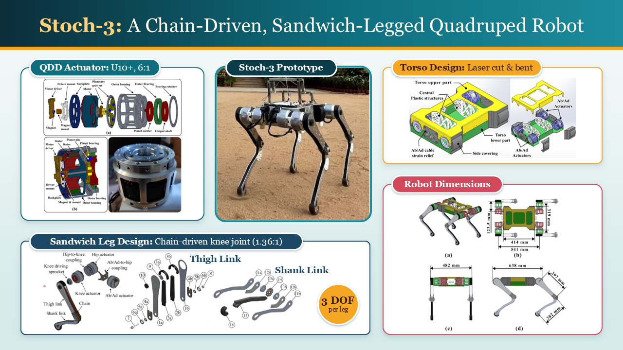
This paper introduces a chain-driven, sandwich-legged mid-size quadruped robot designed as an accessible research platform. The design prioritizes enhanced locomotion, improved actuation reliability and safety, and simplified, cost-effective manufacturing. Locomotion performance is improved through a sandwiched leg architecture and dual-motor configuration, reducing leg inertia for agile motion. Reliability and safety are enhanced using robust cable strain reliefs, motor heat sinks for thermal management, and mechanical limits to restrict leg motion. The design incorporates quasi-direct-drive (QDD) actuators and low-cost fabrication methods such as laser cutting and 3D printing for rapid prototyping. The 25 kg robot is built under $8000, providing an affordable quadruped research platform. Experiments demonstrate trot and crawl gaits on flat terrain and slopes. We also open-source the mechanical designs.
Technical Diagrams
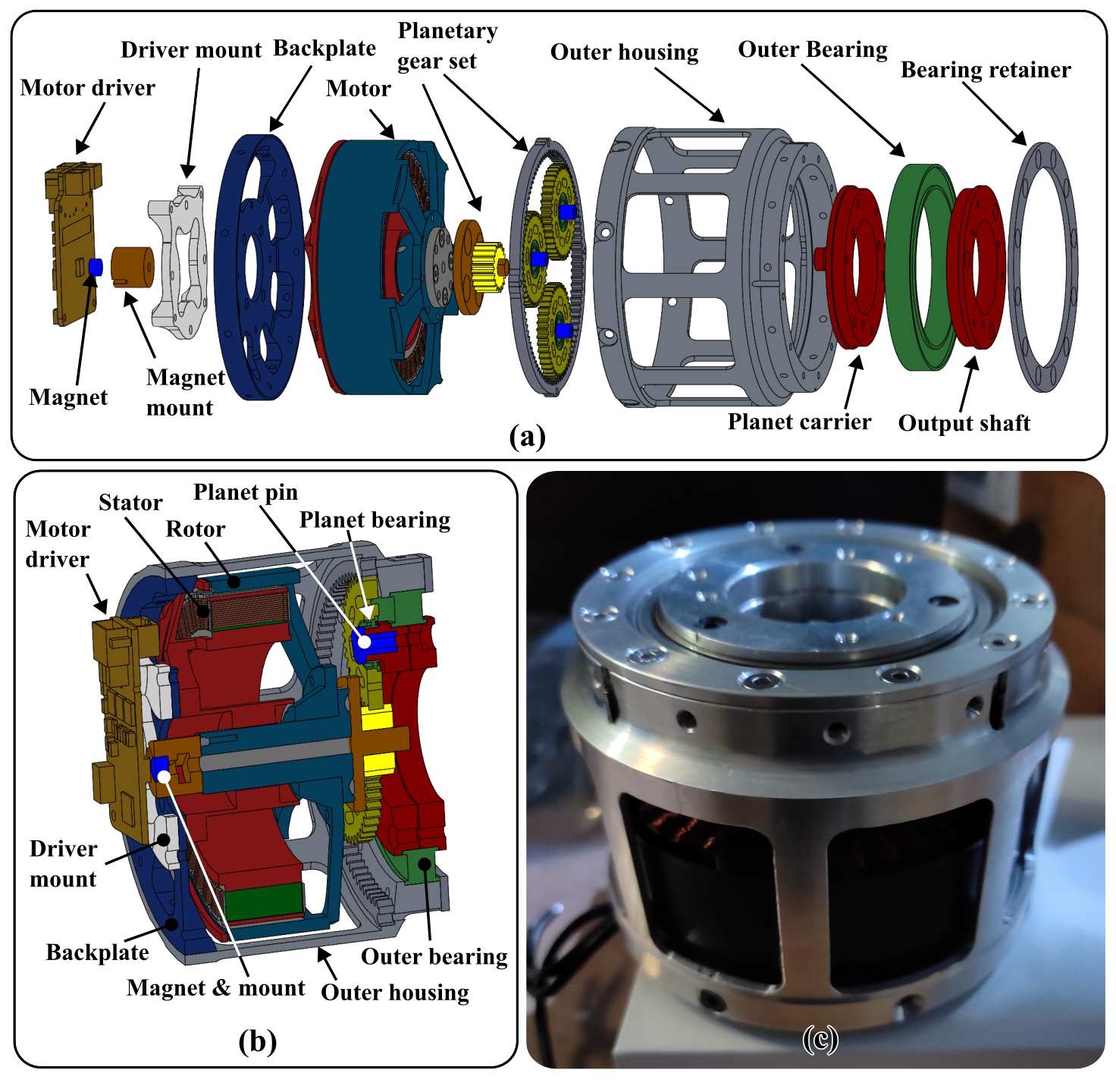
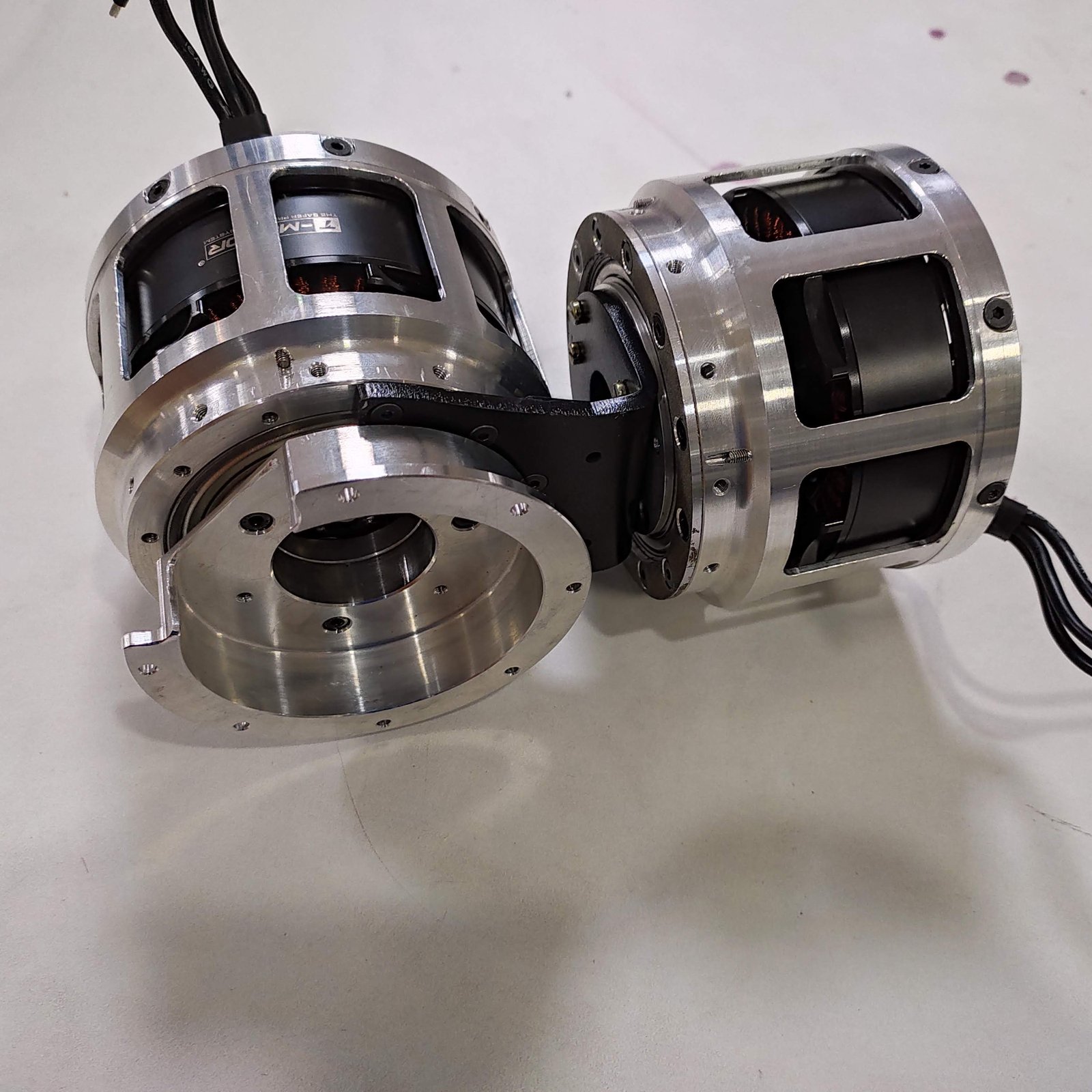
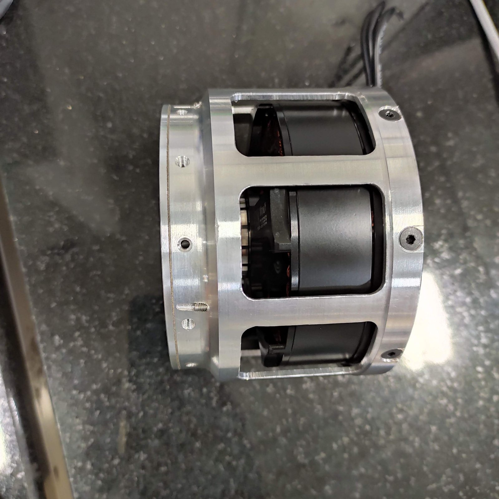
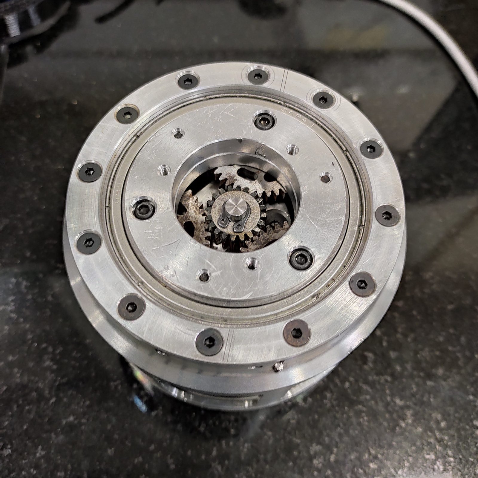
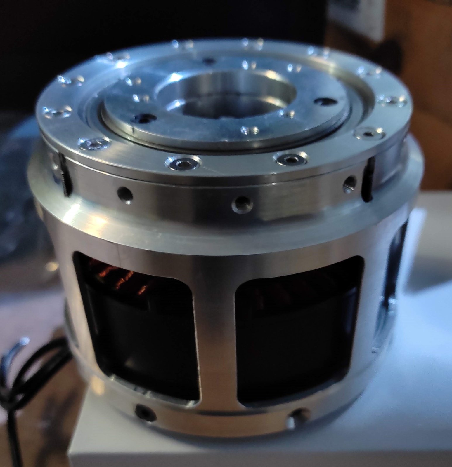
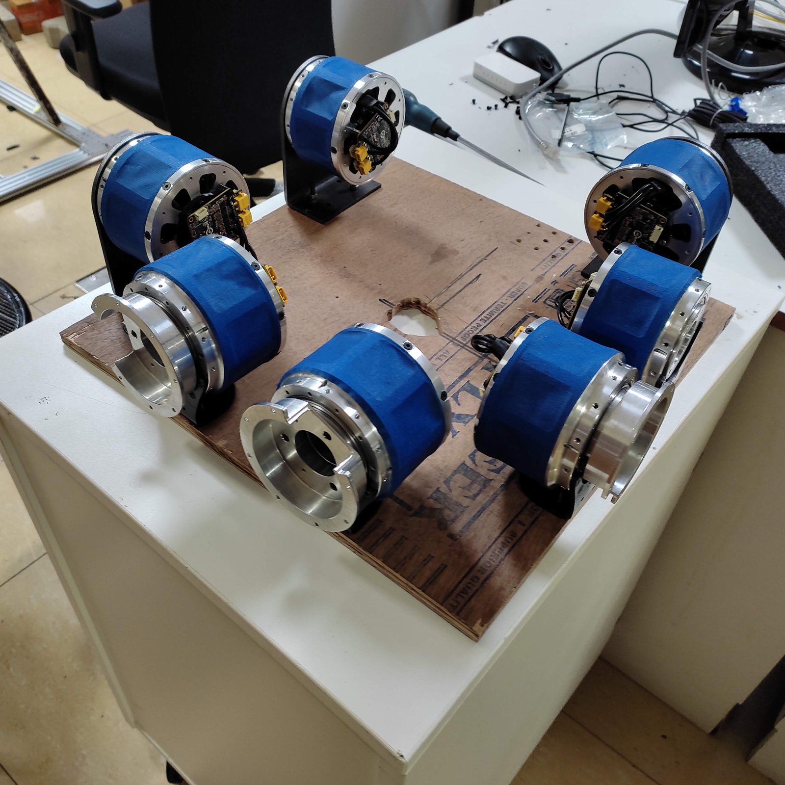
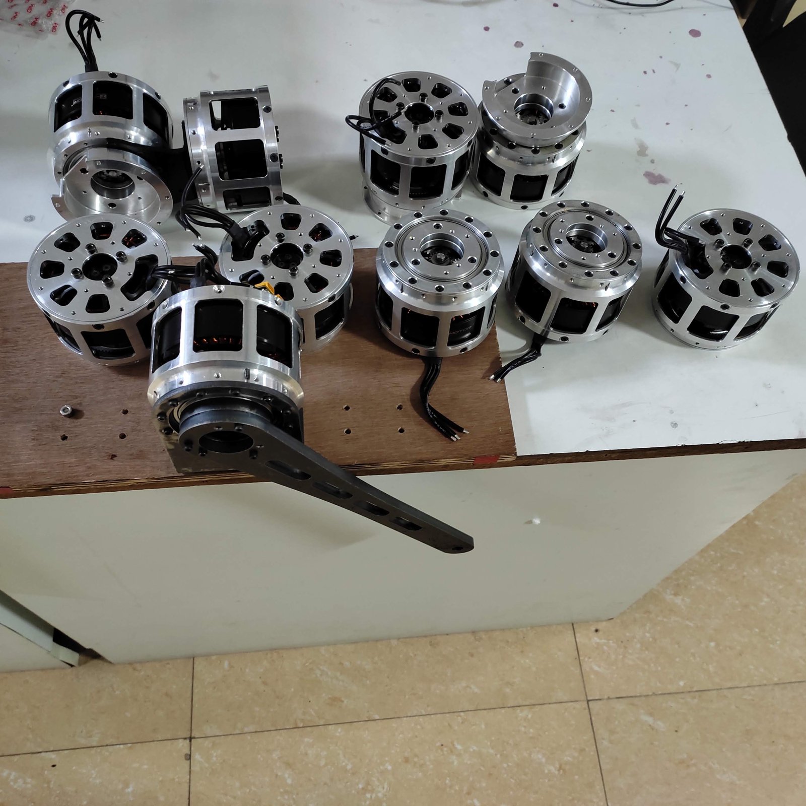
QDD Actuator: (a) Details of the actuator design; (b) Cross-section view of actuator; (c) Manufactured actuator
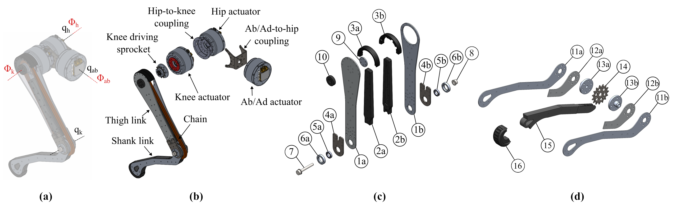
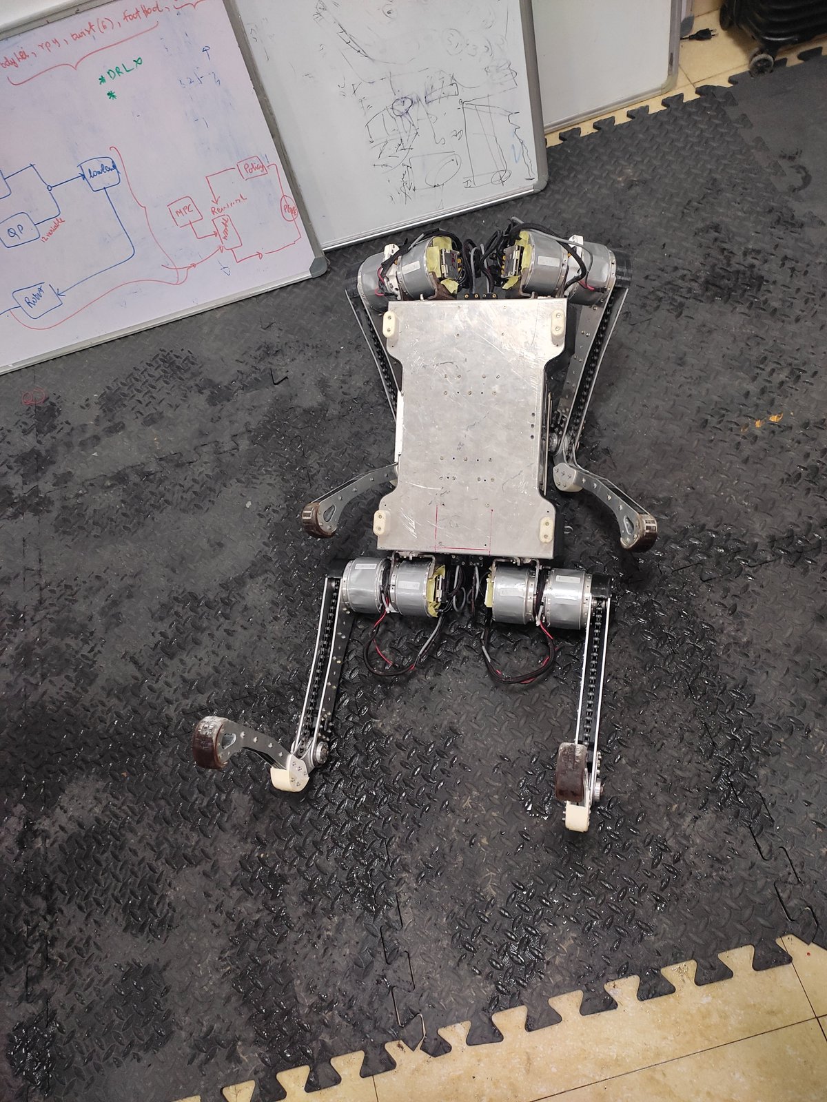
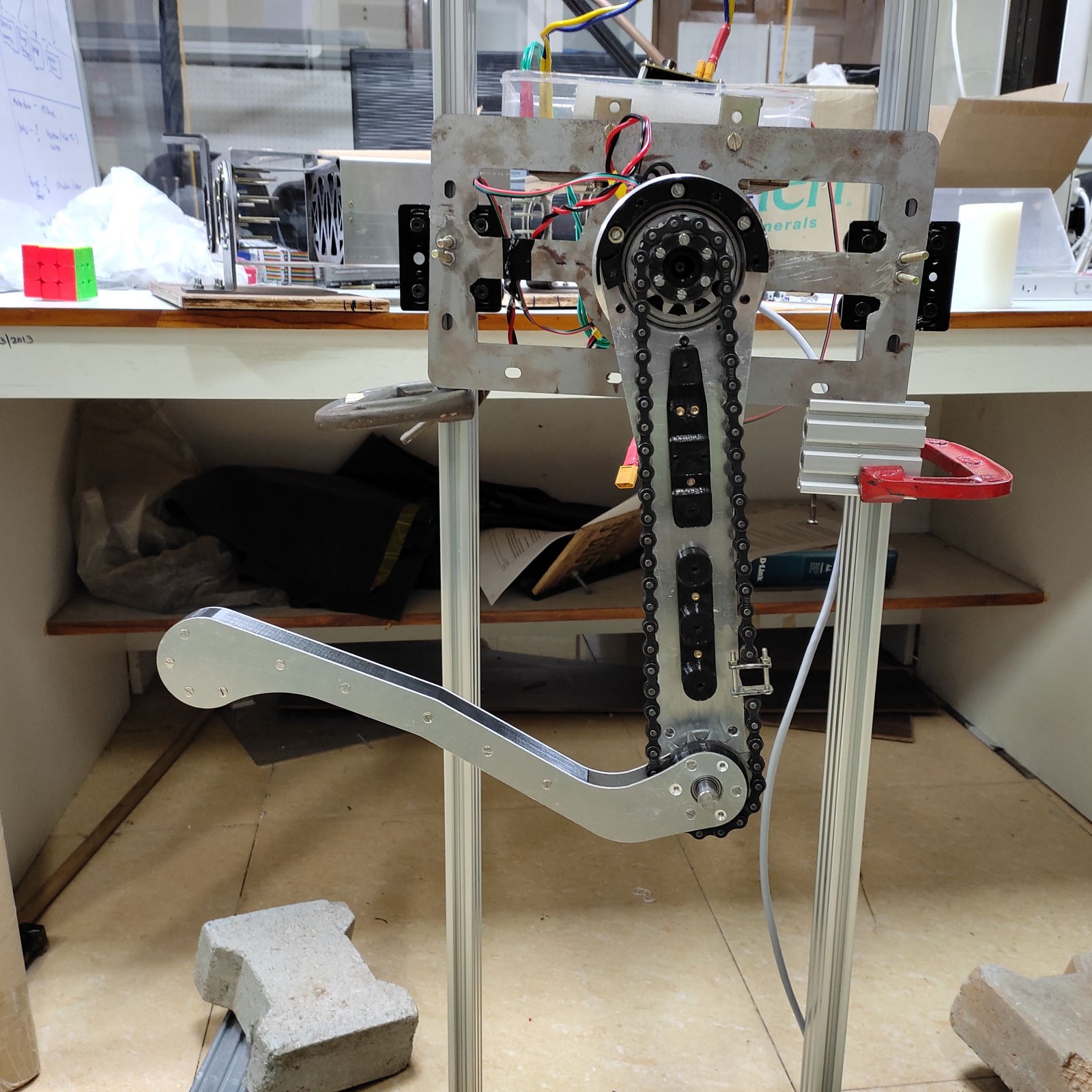
(a) Joints and Actuator Axes; (b) Details of Leg Design; (c) Details of Thigh Link: (1a), (1b): Al Sheets; (2a), (2b): Central spacers; (3a), (3b): Upper spacers; (4a), (4b): Thigh strength plates; (5a), (5b): Knee bearings; (6a), (6b): Knee bearing blocks; (7): Knee bolt; (8): Knee nut; (9): Sprocket support shaft; (10): Support shaft fastener; (d) Details of Shank Link: (11a), (11b): Shank Al-sheets; (12a), (12b): Shank strength plates; (13a), (13b): Knee sprocket couplings; (14): Knee driven sprocket; (15): Shank spacer; (16): Foot.
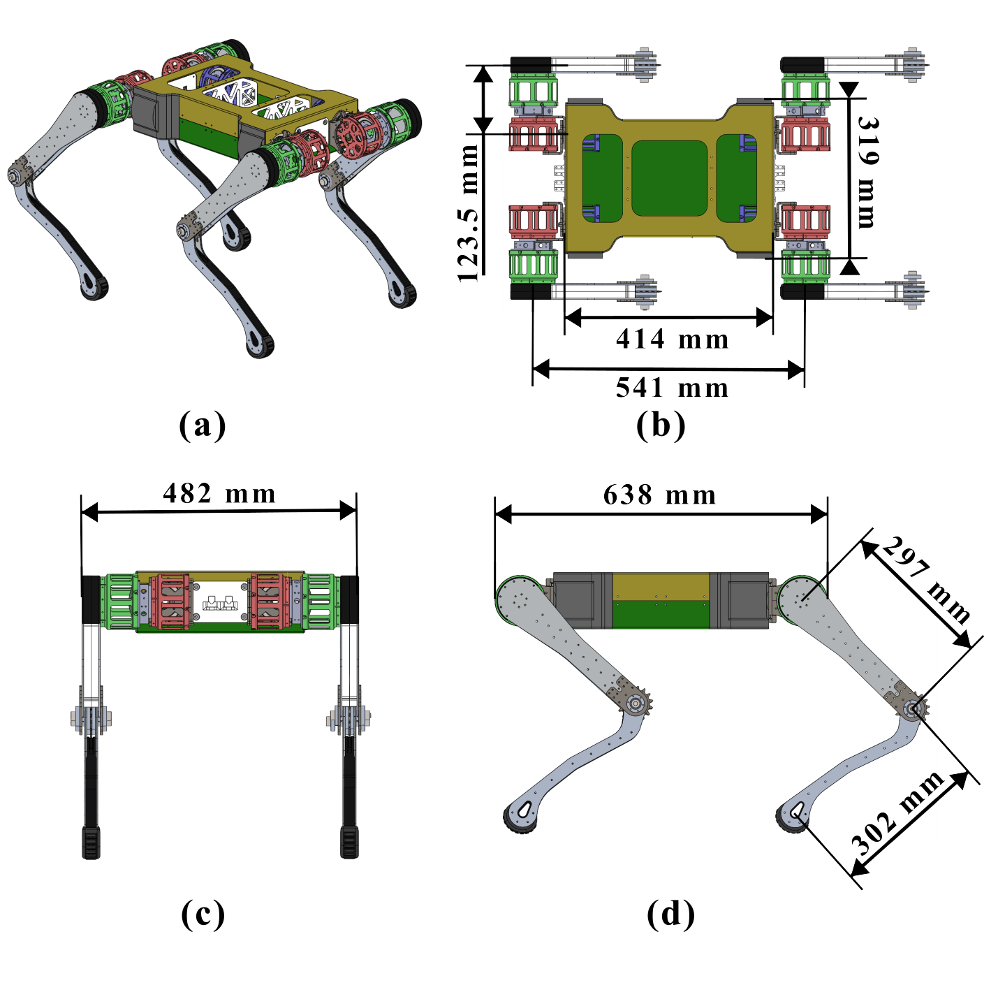
Robot Dimensions: (a) Isometric view of the robot: The torso is made up of two sheet metal parts (yellow and green), with two plastic parts (white and inside the torso) joinging them (b) Top view, (c) Front View, (d) Side view
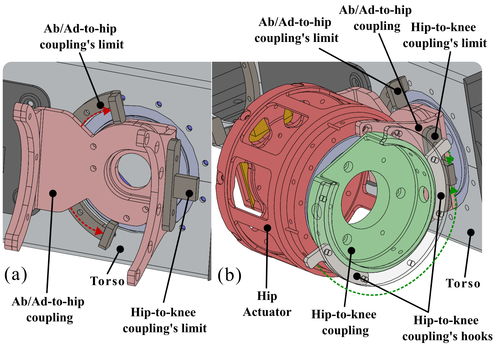
Safety Limits: (a) Ab/Ad-to-hip coupling limit; (b) Hip-to-knee coupling limit
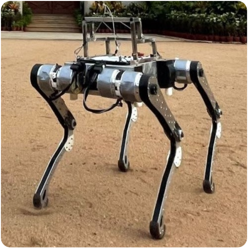
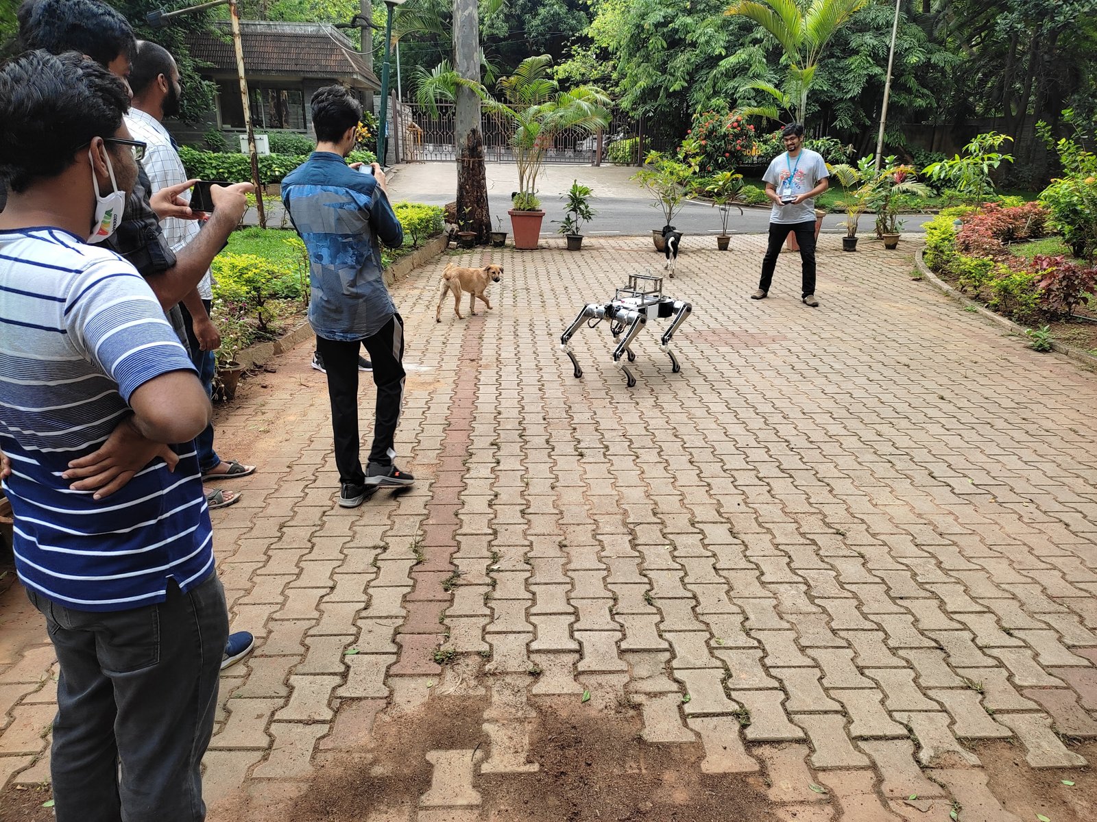
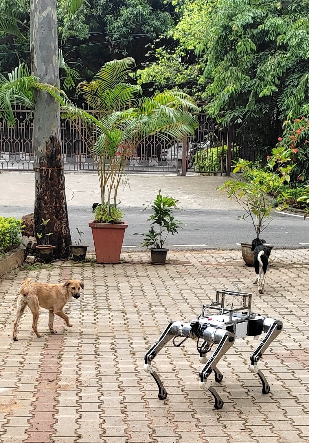
Chain-driven, Sandwich-legged quadruped robot shown standing on the ground.
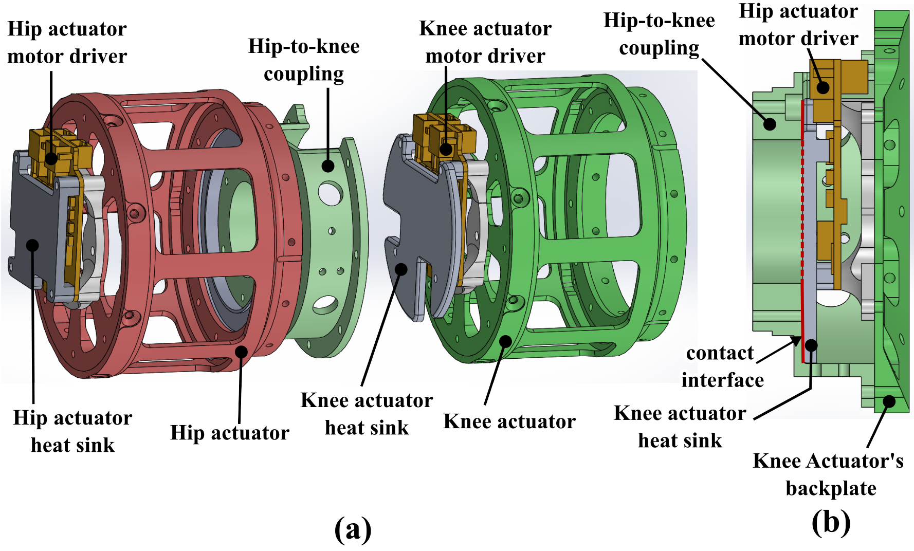
Thermal Management: (a) Exploded view: The knee heat sink goes inside the cavity of the Hip-to-knee coupling; (b) Cross-section view: The knee heat sink touches the Hip-to-knee coupling at the contact interface (red).
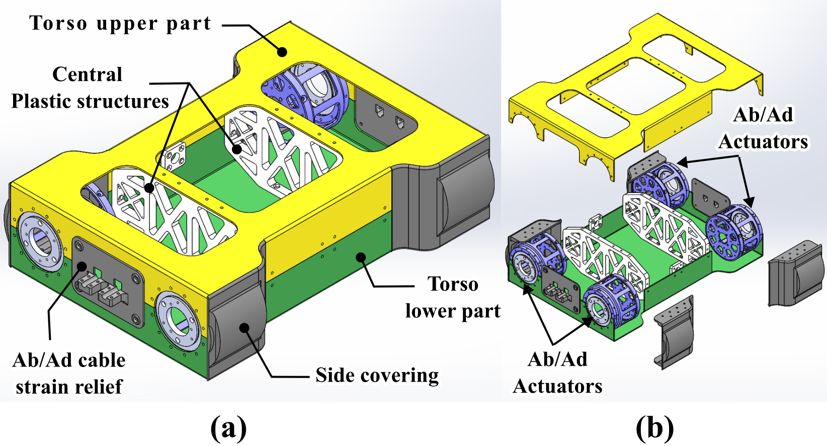
Torso Diagram: (a) Details of Torso design (b) Exploded view of Torso
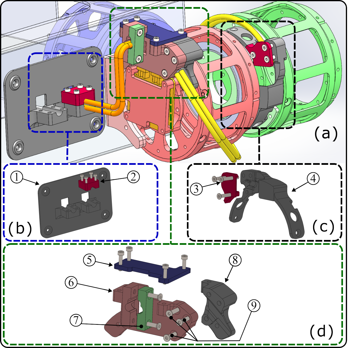
Cable Strain Reliefs: (a) Anatomy of cables and strain reliefs; (b) Ab/Ad strain relief: (1) mounted on the torso, (2) fastens the Ab-Ad actuator wire (orange); (c) Knee strain relief: (4) mounted on the hip-to-knee coupling, (3) fastens the Hip actuator wire (yellow); (d) Hip strain relief: (8) and (9) mounted on the hip actuator, with fasteners (6) and (9) for the Knee actuator wire (yellow), (7) for the Ab-Ad actuator wire (orange), and (5) supporting from the top.
Video Presentation
Gallery
BibTeX
@misc{singh2026chaindrivensandwichleggedquadrupedrobot,
  title={A Chain-Driven, Sandwich-Legged Quadruped Robot: Design and Experimental Analysis},
  author={Aman Singh and Bhavya Giri Goswami and Ketan Nehete and Shishir N. Y. Kolathaya},
  year={2026},
  eprint={2503.14255},
  archivePrefix={arXiv},
  primaryClass={cs.RO},
  url={https://arxiv.org/abs/2503.14255}
}